Overview#
The EVOX1 is a 3.3V logic microcontroller. Sensors will need to be 3.3V compaitable for correct operation. Although the device is a 3.3V logic microcontroller, it has a 5V rail on the servo ports to provide sufficient power to the servos connected.
Hardware Features#
The EVOX1 boasts the following features:
4 x EV3 Motor Ports
4 x Motor Ports with Encoder (shared pins with EV3 Motor Ports)
8 x Servo Ports
8 x I2C Multiplexed Ports
4 x EV3 Sensor Ports
8 x GPIO Ports (shared pins with EV3 Sensor Ports)
2 x UART/ SPI hybrid port
2 x I2C port
4kHz Buzzer
128 x 64 - 1.54 inch OLED Display
Programmable Button
RGB LED Indicator (shared pins with Programmable Button)
Bluetooth Classic via inbuilt HC-05
Bluetooth Low Energy 5.0
Integrated Wi-Fi 4 (802.11b/g/n, 2.4GHz)
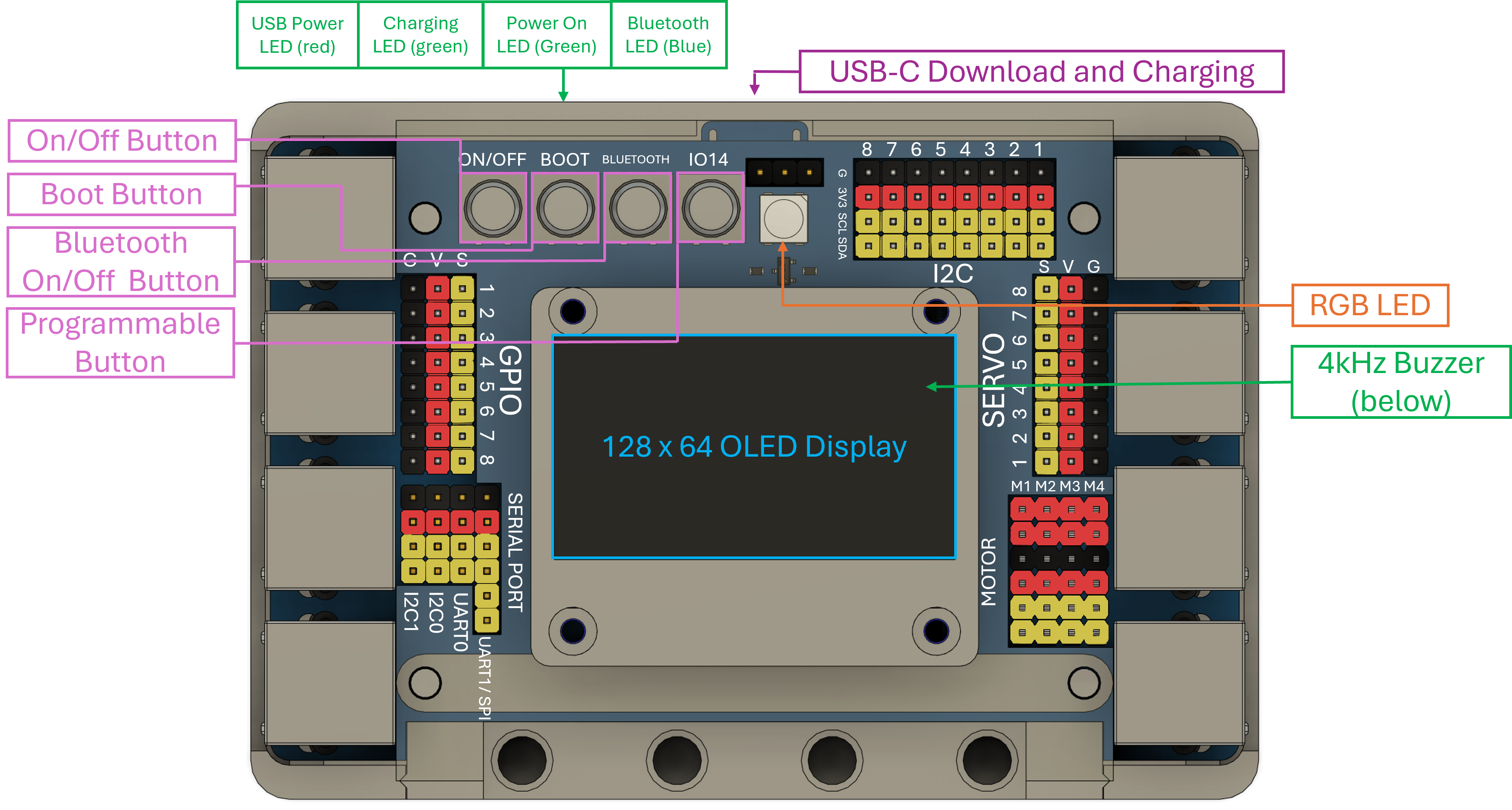
On-Board Peripherals#
Peripheral |
Description |
|---|---|
Power Button |
On momentary press turns the EVOX1 onOn long press turns the EVOX1 off |
Boot Button |
On momentary press puts the EVOX1 into normal modeOn long press puts the EVOX1 into bootloader mode |
Bluetooth Button |
On momentary press turns the Bluetooth onOn long press turns the Bluetooth off |
Programmable Button |
Button that can be programmed
Must be used as
INPUT_PULLUPConnected to the same
IO14 as the RGB LED |
USB Power LED RED |
Indicates power going into the EVOX1 from the USB-C port |
Charging LED GREEN |
Steady ChargingBlinking Unable to chargeOff Battery is full |
Power On LED GREEN |
Indicates that the EVOX1 is on |
Bluetooth LED BLUE |
Blink Cnce in 2s Bluetooth in command mode / ConnectedRepeated Blinking Waiting for connection / DisconnectedOff Bluetooth is off |
USB-C Download & Charging |
Allows download and charging of power |
RGB LED |
WS2812 RGB LED
Connected to the same
IO14 as the programmable button |
4kHz Buzzer |
Programmable buzzer |
128 x 64 OLED Display |
Programmable OLED Display |
Pinouts#
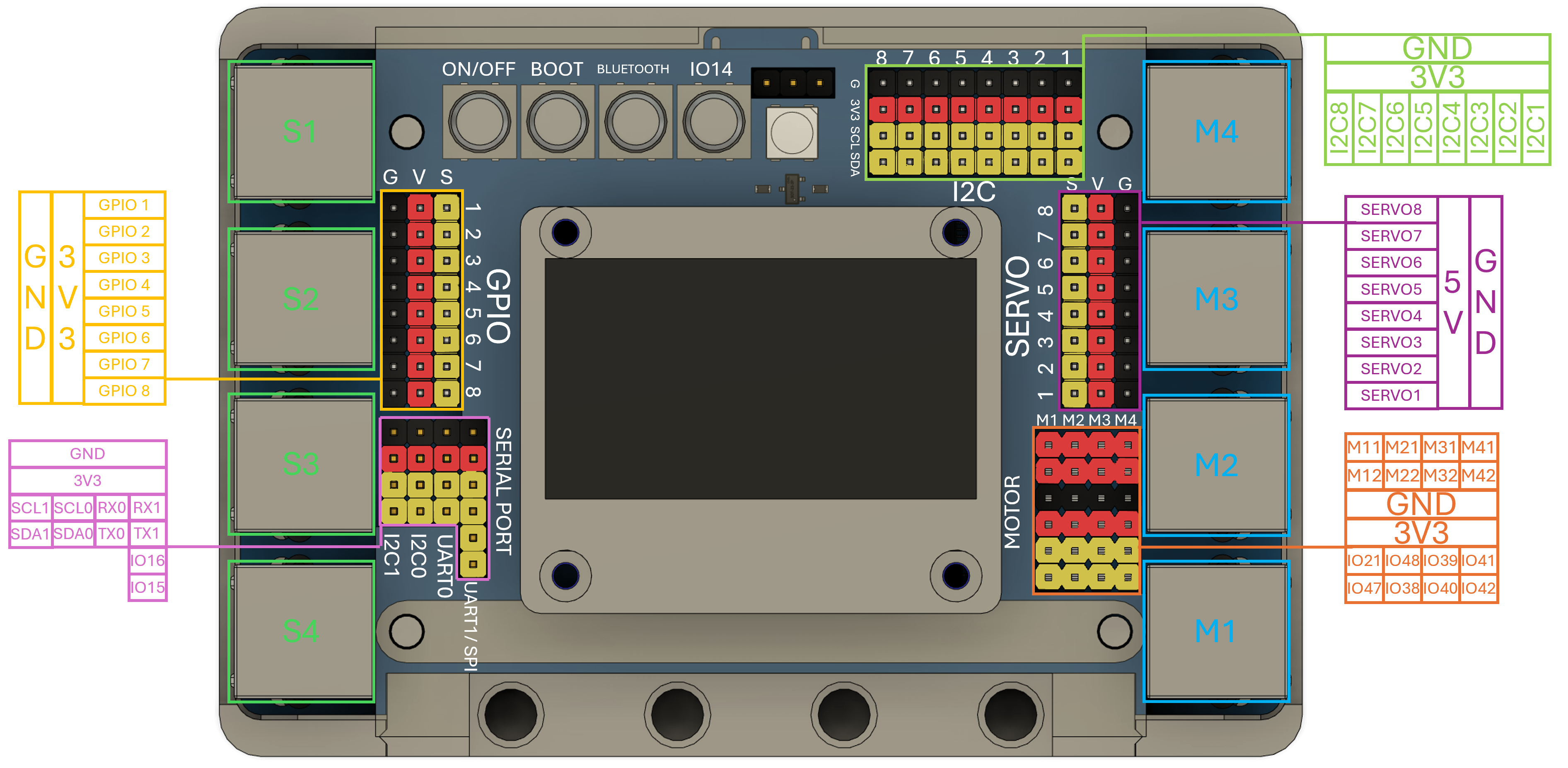
Connecting Hardware#
Peripherals which uses GPIO or SERVO ports have 3-pin connectors
Peripherals which uses I2C or Serial Ports have 4-pin connectors
Motors uses 6-pin connectors
Note
The wires are color coded to match the pin layout of the EVOX1. However do be careful as some peripherals may have their labels covered by the the 3D printed casing. Please see the schematic of the each peripherals.
I2C Wiring#
Colour |
Pin |
Description |
|---|---|---|
Black |
GND |
Ground |
Red |
3V3 |
3.3V Power |
Yellow |
SCL |
Serial Clock |
Yellow |
SDA |
Serial Data |
I2C is wired such that the SDA pin of the host (EVN Alpha) is connected to the SDA pin of a peripheral, and the same goes for the SCL pins.
Motor Wiring#
Colour |
Pin |
Description |
|---|---|---|
Red |
M1 |
Motor output 1 |
Red |
M2 |
Motor output 2 |
Black |
GND |
Ground |
Red |
3.3V |
Power |
Yellow |
IO |
Encoder pin 1 |
Yellow |
IO |
Encoder pin 2 |
GPIO & Servo Wiring#
Color |
Pin |
Description |
|---|---|---|
Black |
GND |
Ground |
Red |
VCC |
Power |
Yellow |
GPIO |
Data |
Caution
The pins on the EVOX1 are color coded. Exercise caution when connecting any hardware to the ports.